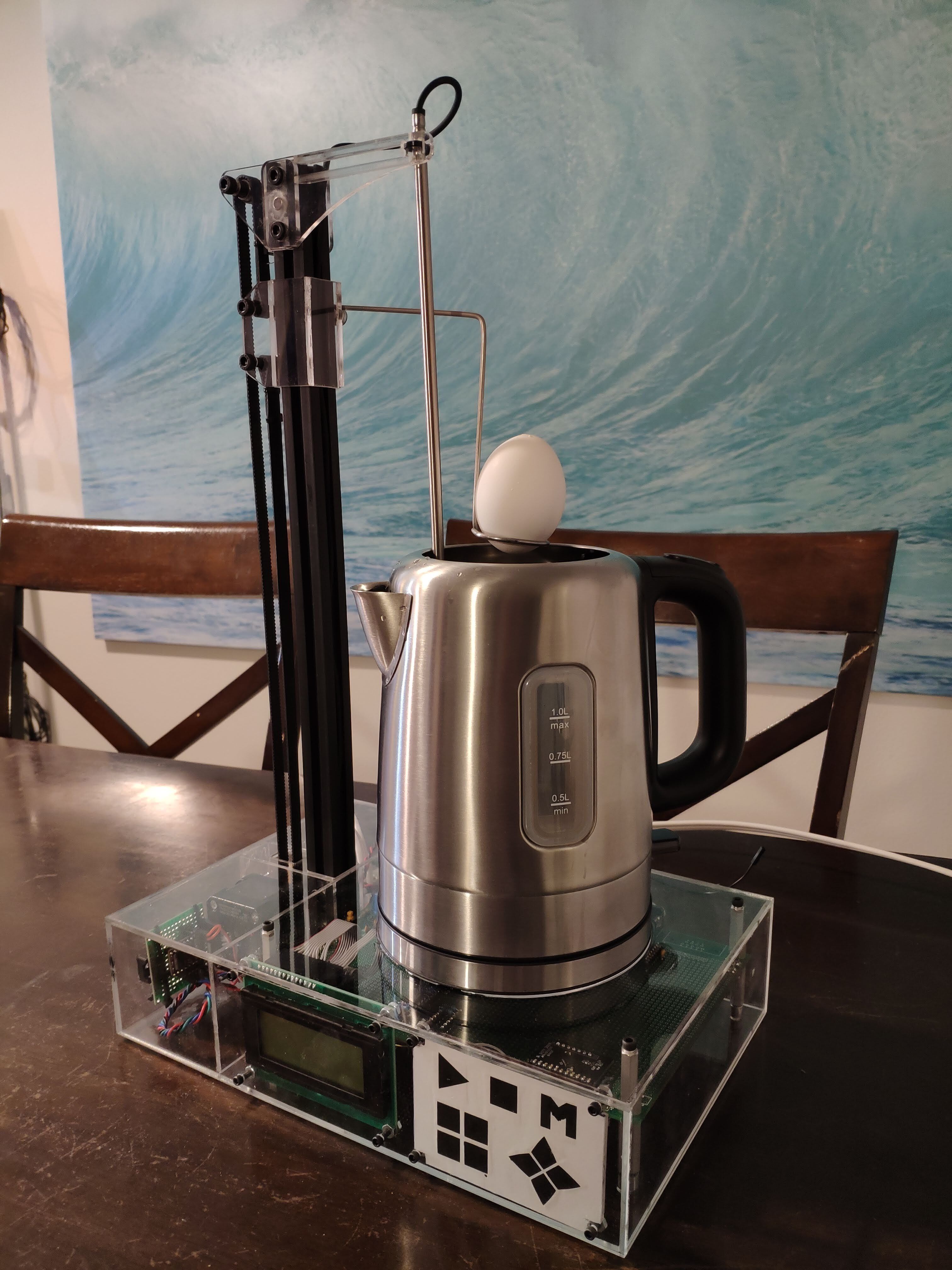
This is the EggBot, my final project for ECEN 5613 - Embedded System Design at the University of Colorado, Boulder. It’s a massively overkill robot for cooking the perfect soft boiled egg (and also making tea).
This will be a (relatively) brief overview of the project. If you want all the information ever, please see the full report here (Giant PDF Warning). I’d like to say thanks Andre Miede for his classicthesis) LaTeX template, which makes that report look so much better than it deserves. If you haven’t used LaTeX before, it’s excellent at making resumes, large documents, and anything that needs consistent formatting and frequent updates. This report is 200+ pages of nearly perfect formatting, and there is no way I could have done it without LaTeX.
ECEN 5613 is centered around building up a wire wrap board featuring an 8051 microcontroller (C51 really, AT89C51) and a number of peripherals. The 8051 is advantageous because it fully exposes the address lines of the processor for both program and data memory, which allows the students to perform logic analyzer captures on the lines and watch the fetch process. This is great for learning, but also great for debugging since the AT89C51 does not have a debug interface.
The class requirements for the project are that it must include both new hardware and new software of sufficient complexity. Everything else is left to the student. Many students chose use a different platform to develop their final project on, some even designing platforms from scratch. I decided to use my 8051 board I had built over the semester, as I had dedicated many hours to it already and it seemed unlikely I would ever have occasion to use it in the future. From this came my personal goal: Integrate the 8051 board in such a way that it can be displayed and used frequently in my home. Somehow, this ended up being a soft boiled egg making robot.
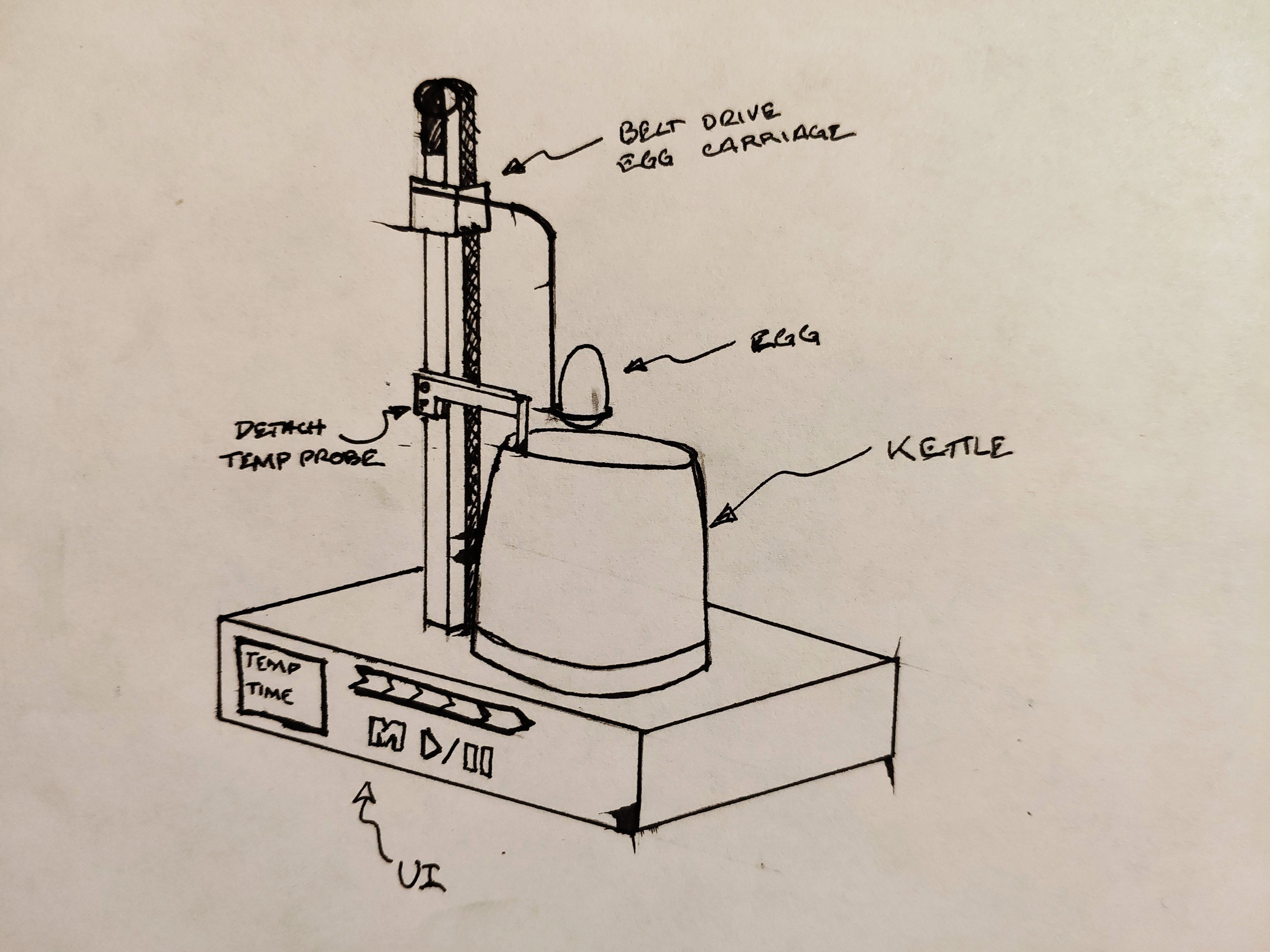
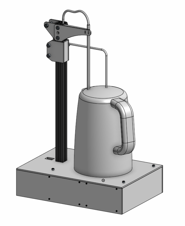
The robot has a single actuator, made up of a stepper, Misumi extrusion, and GT2 Belt. The actuator can raise and lower a basket into the kettle, which is where the egg rides. The kettle is powered through a relay and monitored by a NTC temperature probe, for closed loop temperature control. There is a small user interface on the front of the bot with an LCD and a capacitive touch keypad.
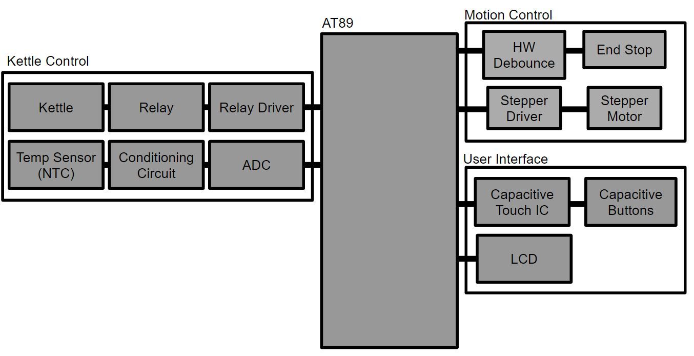
The basic hardware block diagram is shown below:
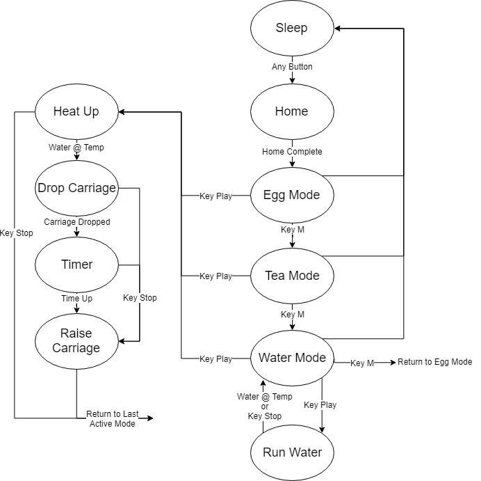
The basic software state machine is shown below:
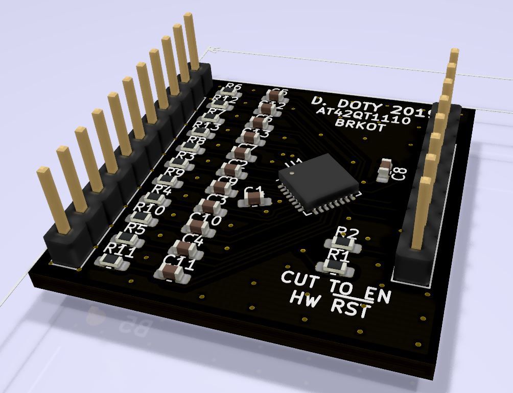
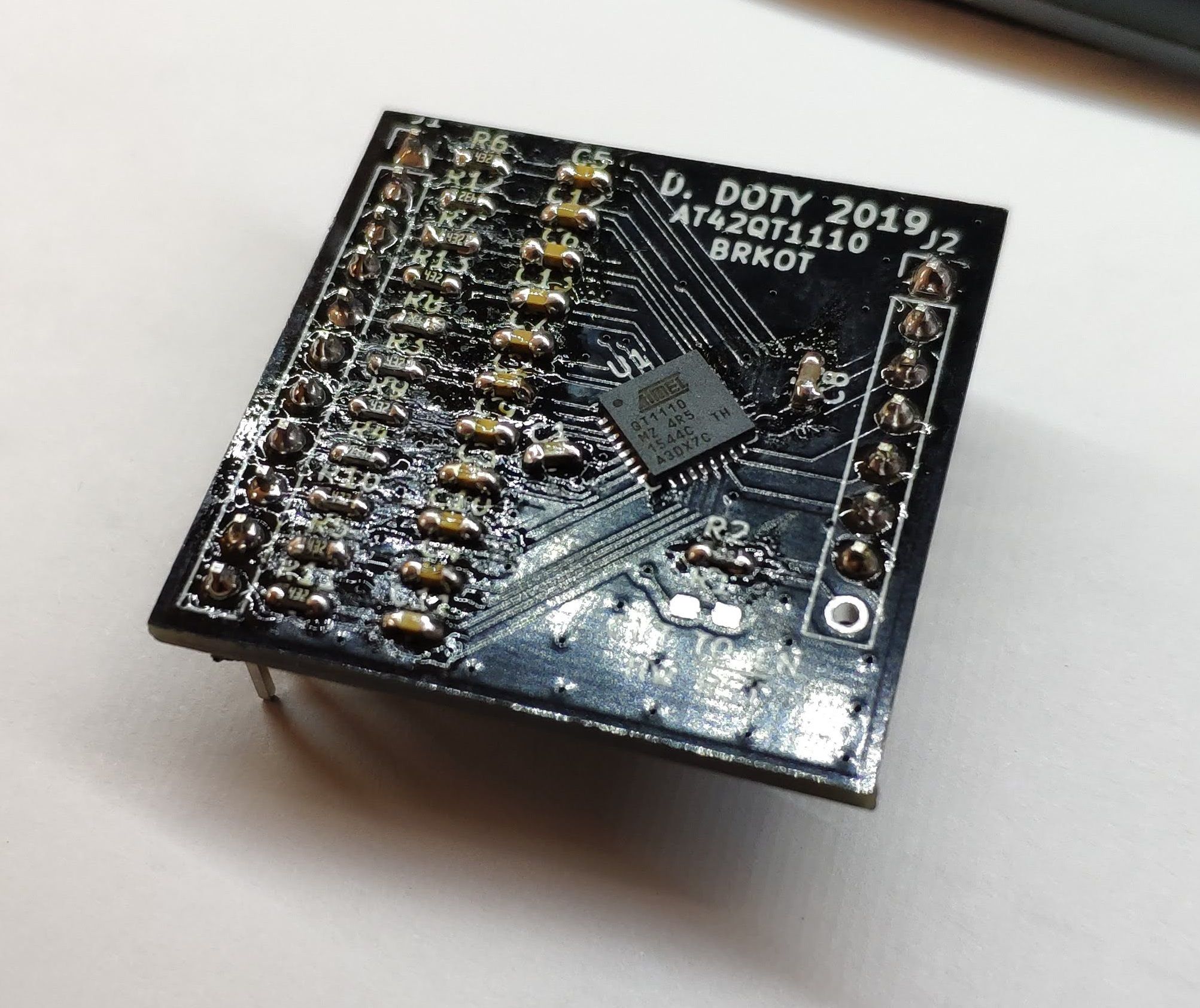
Here’s the breakout board I designed for the AT42QT110 capacitive touch chip:
One aspect of the project that proved very difficult was generating the commands for the stepper motor. I wanted to use an acceleration based planner rather than stepping at a fixed frequency (which would be easy with hardware PWM). I created a planner function that takes movement commands and translates them into times between steps. These are then transferred to a timer ISR via a double buffer, and the ISR executes a step and then resets the timer using a value from the double buffer.
To get this to work on the 8051 required extensive assembly level optimization. The original C implementation of the ISR was 453 assembly instructions. At full velocity, this equates to 1.1 million instructions per second that the ISR needs to execute. With the AT89 running on a 11.0592 MHz crystal, it can only execute 921 thousand instructions per second, meaning the ISR overruns processor capacity. Through assembly level optimization, I was able to get the ISR down to 52 instructions. This makes me sound super awesome, but in reality the SDCC compiler (Small Device C Compiler) is not super polished and can leave a lot of room for optimization.
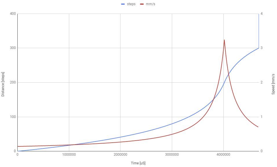
Here is a graph of a movement calculated from step times output by the step generator. Originally I wanted to do trapezoidal velocity profiles (fixed acceleration), but found that dividing the time between steps produces S curve velocity profiles. This is not only smoother, but I think less processor intensive for step generation.
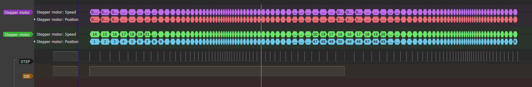
Here is a logic analyzer capture of the step commands going to the driver on the board.
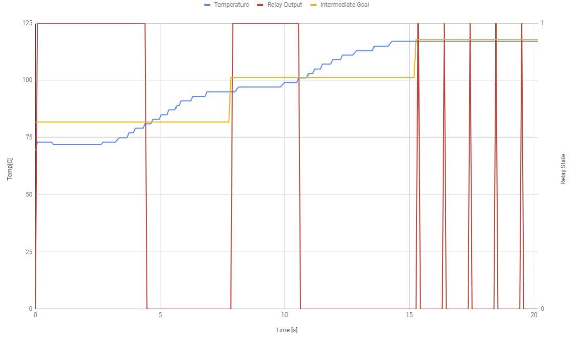
Another difficulty with the implementation was temperature control of the kettle. Originally I had planned to used bang-bang control with hysteresis, but this actually showed massive overshoot in testing. I settled for a sort of modified bang-bang, where the set point is gradually increased to the final set point. This reduces the overshoot significantly, but is still not great. This is definitely an area I’d like to improve.
I’m thinking I’ll do some sort of step response to try and estimate the thermal mass of the water in the kettle, and then use that to calculate how long to turn the heater on to hit the set point with minimal overshoot. This should allow for tight control without toggling the relay like a maraca. You could think of this like hitting a ball with a baseball bat. First you hit the ball lightly and measure how far it goes. If you know how hard you hit it and how far it went, you can now estimate how much the ball weighs. Once you know how much the ball weighs, you can calculate exactly how hard to hit it to get it to go a specific distance.
Thanks for reading my little summary of my final project. I really enjoyed making it and I hope you liked reading about it. I think it’s a great example of what you can do with the right mix of Mechanical and Electrical Engineering. If you want a much, much longer explanation, check out the full report here (Giant PDF Warning).