N64 BT Update
More N64controller 13 Mar 2014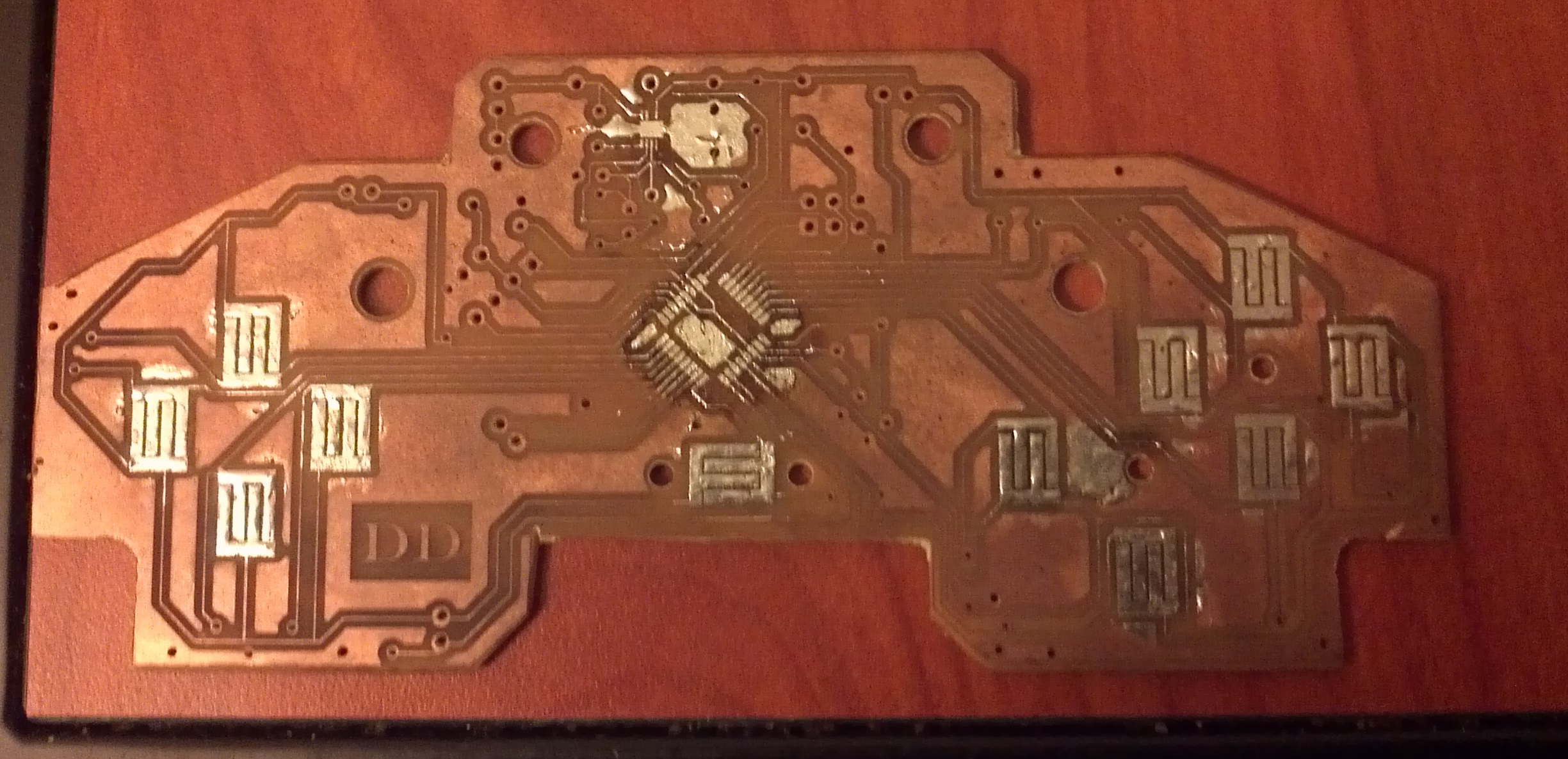
Ah, the N64 controller. An exercise in learning. I’ll be straight with you, I didn’t do this right. I started this project at a time when I didn’t know all that much about what I was doing. But I think it was the best possible way for me to jump in and learn a lot all at once. But as a learning experience, it was full of errors. Lets go down the list.
Interrupts
Interrupts are the way a game controller should be done. When I planned this out, I was going to scan all the buttons continuously. This sucks. Scanning continuously means that the microcontroller can never be put in a sleep mode, meaning battery life will be terrible. There’s also a chance that a button input could be missed. In this case, the 328P has 3 pin change interrupt flags covering pins 23-16, 14-8, 7-0. Each flag covers 7 or 8 pins, for 23 total (what’s up with 15? It isn’t listed). We lose one of those as a reset pin. Two more of those are lost to a crystal input. So now we’ve got 20 total. The N64 has 14 buttons. We need two ADC pins for the joystick, and 3 or 4 more for SPI (Depending on if you use SS or not, but it isn’t needed since there’s only one slave). We’re now need 19 or 20 pins. Just enough for the 328P. But the interrupts are enabled for whole ports, so we have to line up the ADC and SPI pins on one port. This could work. But I unfortunately didn’t set up my board with this in mind. I could also use a TCA8418 from Texas Instruments. This would support up to 80 buttons in an 8x10 keypad, a bit overkill.
Pullups
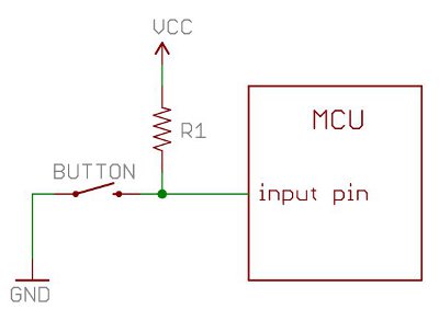 Pullups ensure that the button signal is either high or low. When the button isn’t pressed, it is weakly pulled high by the resistor. When the button is pressed, the current all runs to ground, making the microcontroller input low. This is pretty standard, and I did include this in my board. Downside is, the 328P has internal pullups. You can enable these internal pullups and have no need for external pullups that I had clogging up my board. This would have significantly eased my layout woes.
Level Shifting
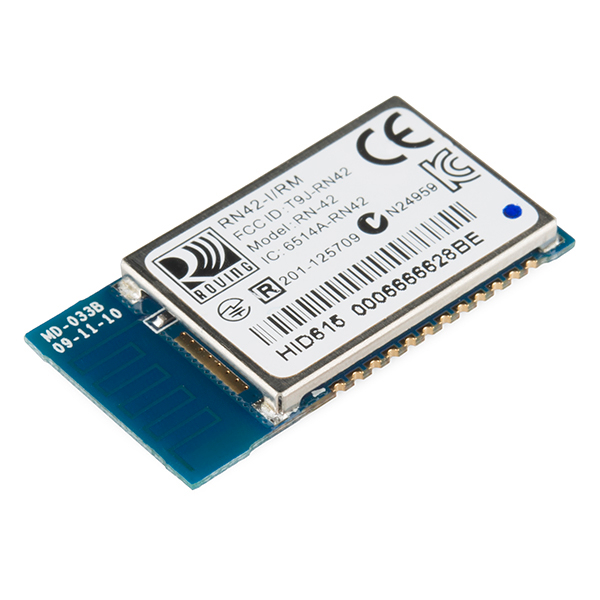 The bluetooth module I chose was the RN-42. This module is pretty awesome because it automatically appears as an HID module. It automatically appears as an human interface device, which means it won’t need a driver computer side. The module runs on 3.3v and can sleep at 26uA, with a variety of other sleep modes. Pretty sweet for a battery powered game controller. It can also be configured to act as a gamepad input to the computer. The issue comes up with SPI communications. My ISP runs at 5v and this module runs at 3.3v. The SPI bus is both used for the module and the ISP, so I really needed a method to disconnect the BT module for programming.
Layout
My layout was poorly done. I had right angle traces, which is a layout no-no. The additional lines for pullups clogged up the board. There are a few places where many small traces are side by side, which allowed them to short or be scratched off.
Trace Widths
The traces were really small to fit near the smaller ICs. I really should have made the traces thicker. The problem is that these traces are so thin, they can be scratched off with a soldering iron on accident. The real issue here is that I don’t have a solder mask. With a mask, the clearances can be tighter without worrying about solder bridges. As it stands, its bridge city. This is another reason why professional boards are probably better.
DominicDoty.com and all work shown in it is licensed under a Creative Commons Attribution-NonCommercial-ShareAlike 4.0 International License.